
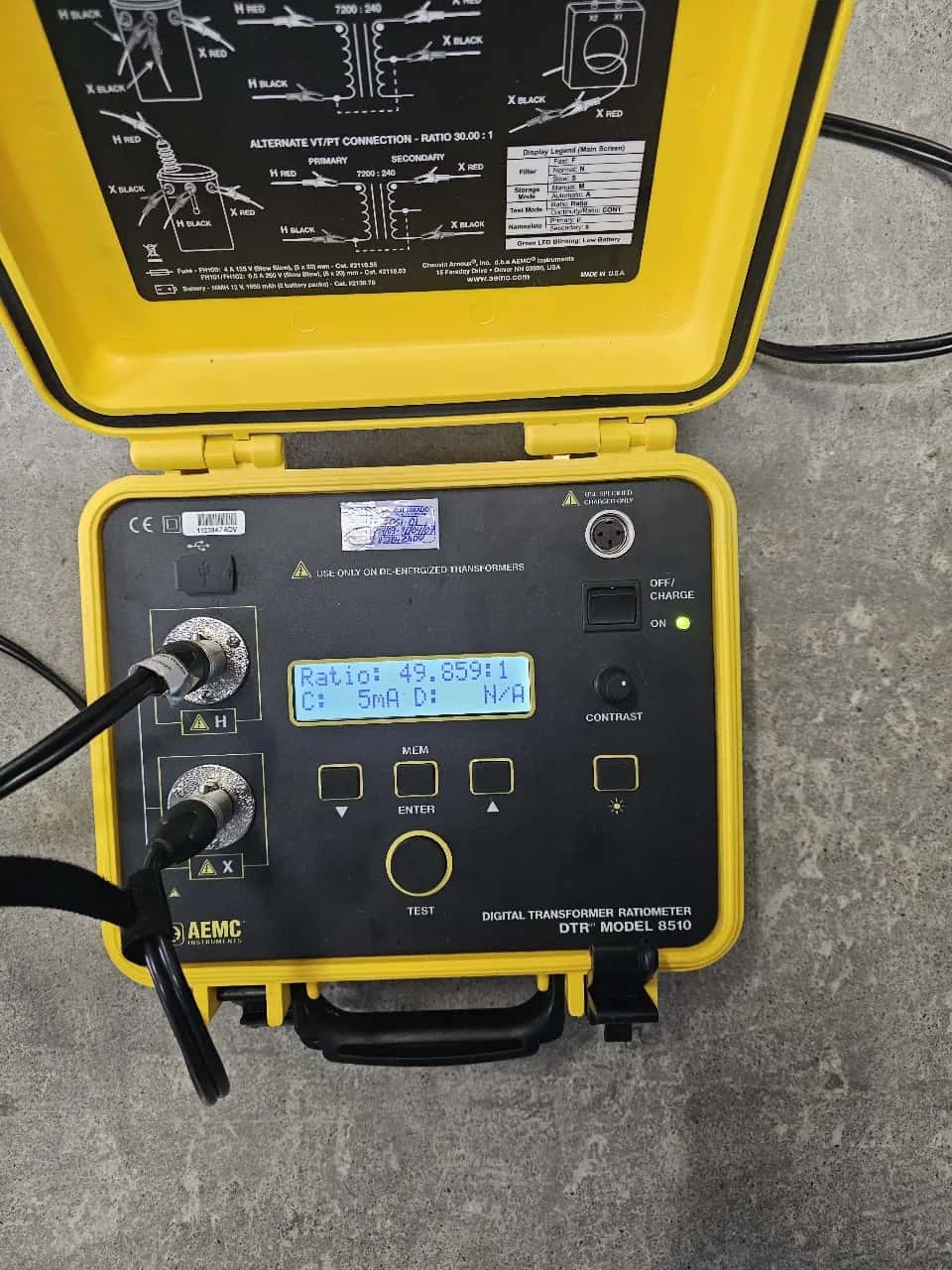
Electrical test
Transformer turns ratio test (TTR)
Verifies the turns ratio between high- and low-voltage windings to detect shorted turns, tap-changer faults and connection errors.
TTR measures the ratio between the number of turns of the primary and secondary windings by applying a known voltage on the high side and measuring the induced voltage on the low side. The result is compared against the expected ratio, calculated from the nameplate according to the vector group, the test connection and the tap position. The tolerance is set by IEEE C57.12.00: ±0.5% of the nameplate ratio on all taps, with exceptions such as windings where the volts per turn do not allow that adjustment, in which case the ratio is taken to the nearest turn. IEEE C57.12.90 is the test code that defines how it is measured. For in-service units the reading is also compared between phases, against the factory report and against the asset history.
A ratio out of tolerance reveals shorted turns, incorrect connections, or a tap changer that fails to make contact in some position. That is why the test is run at ALL tap positions, not just the nominal one: the pattern of variation between positions is what diagnoses the condition of the changer.
The measurement records the ratio per phase and per tap position and, together with excitation current and phase displacement, helps tell a winding problem from a core or tap-changer problem. Every result is recorded in the protocol, compared against nameplate, between phases and against asset history.
What TTR diagnoses
Shorted turns
A ratio lower than nominal in a winding indicates shorted turns due to inter-turn insulation degradation.
When it applies: After an overvoltage event, discharge or through-fault.
Tap-changer fault
Irregular variation of the ratio between tap positions reveals dirty, worn or open contacts in the OLTC/DETC.
When it applies: Maintenance of transformers with an on-load tap changer.
How we run the test
Outage
Transformer de-energized and isolated, with grounds removed from the windings to be measured.
Measurement
Ratio, excitation current and phase displacement at all tap-changer positions.
Comparison
Against nameplate ratio, between phases and against asset history.
Protocol
Report with percentage deviation per position and an acceptance verdict.
Frequently asked questions — transformer turns ratio test (ttr)
What is the transformer turns ratio (TTR) test for?
It verifies that the turns ratio between windings matches the nameplate. It detects shorted turns, open windings, reversed connections and tap-changer faults. It is one of the first acceptance tests after a repair and part of maintenance diagnostics.
What is the acceptable tolerance in a TTR test?
The tolerance is in IEEE C57.12.00: ±0.5% of the nameplate ratio on all taps, with exceptions for windings where the volts per turn do not allow that adjustment. IEEE C57.12.90 defines the test method. The applicable edition is the one for the unit. A deviation out of tolerance is investigated before energizing, and a difference between phases is reviewed considering the vector group, the test connection and the measurement conditions; on its own it does not prove damage.
Is it measured at every tap-changer position?
Yes. The test is run at each tap-changer position because the pattern of variation between positions is what reveals whether the changer makes contact correctly. Testing only the nominal position hides changer faults.
Does the transformer need to be out of service?
Yes, the TTR test is performed with the transformer de-energized and the windings isolated. It is coordinated with the asset outage, usually together with the rest of the electrical test protocol.
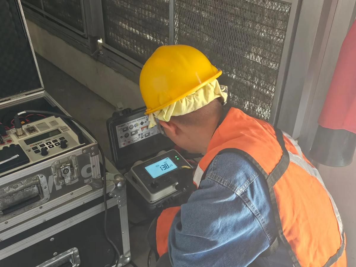
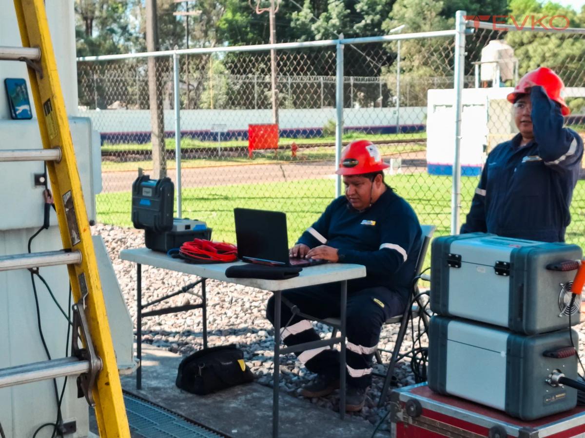
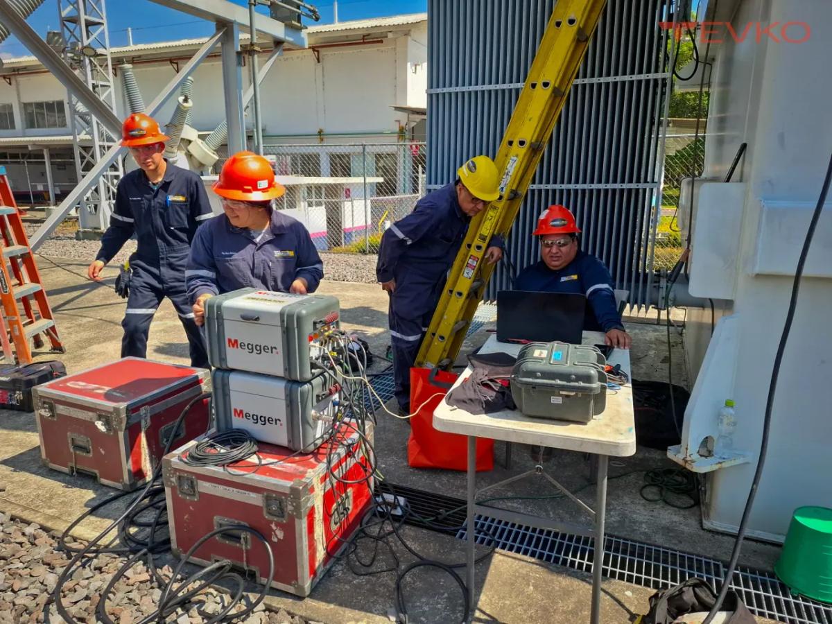
Transformer turns ratio test (TTR) in images
Related tests and services
Talk to a transformer specialist
Tell us about your asset so we can define the assessment scope and prepare a tailored quote.